 DENEB SYSTEMS
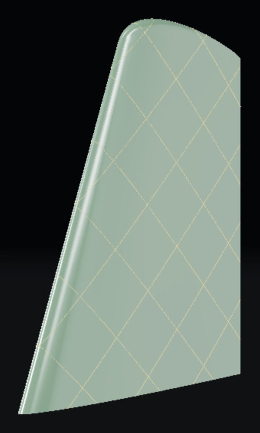
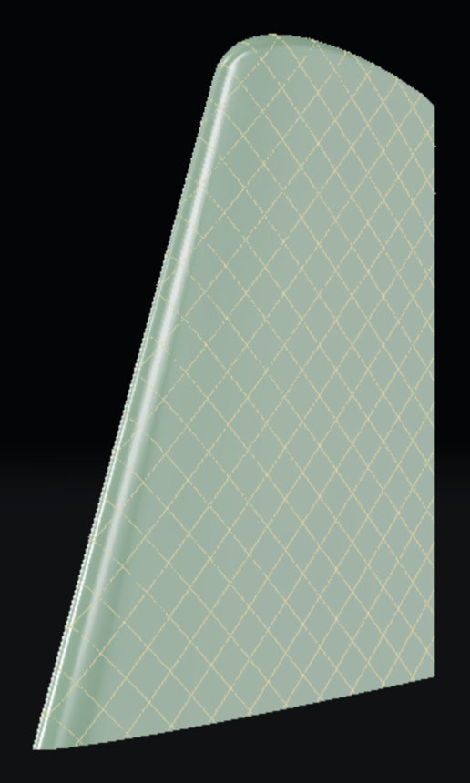
Rib pitch
Default 30 mm
Distance between parallel ribs. Smaller pitch packs more members and more plastic; larger pitch lightens the truss.
Deneb Systems / 3D printing
3D-printing software for UAV wings. Convert a solid STL into a vase-mode mesh — one wall the slicer can spiral, optional diamond ribs for stiffness. It runs in this browser. Nothing is uploaded.
Open the studio
01
Drop an STL, or a sliced .3mf to copy layer height. The file stays in this tab.
02
Rib pitch and angle draw on the model. Click a face to stand that surface on the bed.
03
One hole-free loop per layer, with a diamond truss inside. Download an STL the slicer can vase.
Printed airframes
Deneb aircraft are largely 3D printed. Mass is the design. Filling a wing or fuselage with infill is cheap stiffness and expensive weight. Vase mode is one continuous extrusion — fewer seams, less plastic — and the internal ribs carry load as a truss instead of a solid. That is the difference between a printed shell and a part that can fly.
Documentation
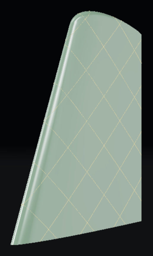
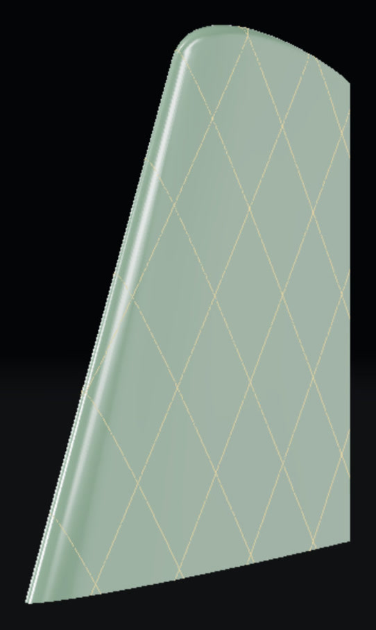
Rib pitch, angle, and scallop are shown on the same UAV wing. The rest change the slice, not a picture of the overlay — match layer height and nozzle to the slicer.
Default 30 mm
Distance between parallel ribs. Smaller pitch packs more members and more plastic; larger pitch lightens the truss.
Default 45°
Rib angle from horizontal. 45° gives a diamond. Higher values lean the members toward span.
Default 0.5
Waves rib depth along its length, 0 to 0.9 of full depth. The member stays continuous — this is how you lighten a rib without cutting it. 0 is a solid rib.
Default off
Skip the lattice. One vase-safe skin, no internal truss. Use when the part is already a shell or you only want the spiral wall.
Default 0.2 mm
Height of each vase loop. Must match the slicer. A mismatch can land a slice on a step and show as a gap.
Default 0.2 mm
Thickness of the layer on the bed. Match the slicer’s first-layer height so the floor and the vase start agree.
Default 3
First N layers are a solid floor: holes filled, no rib slots. Match the slicer’s bottom shell count (Bambu default 3). 0 puts slits on the bed.
Default 0.4 mm
Nozzle diameter. Sets how wide a bead is. Keep it in line with the slicer; slit width is chosen relative to this bead.
Default 0.15 mm
Width of every hairline slit and bridge. Must stay open in the slicer — if it is too narrow the slicer heals the cuts shut and the vase loop breaks.
Default periodic height bands, period 0 (nearest skin)
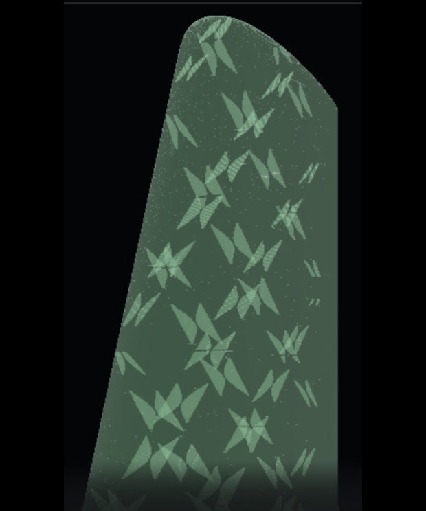
A hole inside the section would make a second loop, so every through-hole in the model is cut open to the outside by a hairline slit. This picks which skin each slit opens on. One skin, the same all the way up, makes a seam line down that side of the part; the modes below spread the openings out. Only holes already in your STL are affected - the generated ribs are always cut from both skins. The drawings are real sections of a 220 mm wing with four 6 mm spar tubes, at two heights; the bright line is the slit and the dot is where it meets the skin.
Default 0 mm
Height of one band for periodic mode: every N mm up the part the holes swap skins. 0 turns periodic mode off, and each hole takes its nearest skin. The other modes ignore it. 10-20 mm is a good start: short enough that no long seam builds up on one skin, long enough that the slit does not jump every few layers.
Needs a period above 0
All holes open to one skin for a band of height, then all to the other for the next band, and so on. The tube is held from both skins along its length, and neither skin carries a seam from root to tip. The usual choice for a spar tube.

Works at any period
Holes in the front half of the section open to one skin, the rear half to the other, at every height. Keeps the slits away from each other when two tubes sit close together.

Works at any period
Neighbouring holes open to opposite skins, at every height. Spreads a row of holes evenly over both skins.

What period 0 gives
Each hole is opened through the thinnest wall, which is the nearest skin. The shortest slit and the least disturbed section, but the opening never moves, so each hole leaves one seam line up one skin.

Two or more STLs
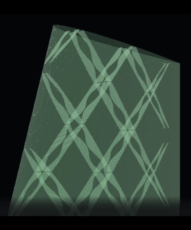
Drop or choose several STLs at once, or use Add a section, and the studio treats them as one wing. Sections exported from the same CAD assembly keep their places; otherwise they are stacked root to tip in the listed order (the arrows change it) and each joint outline is lined up with the one below. The whole assembly is stood on one bed face, then every part is built in that shared frame and dropped to the bed to print, so the rib lattice, the scallops and the hole-side bands run straight on through each joint instead of restarting. Build all parts builds them one after another; download them one by one or as a zip. The drawing plots every rib slot the build cut, near the joint of a two-section tapered wing.

Default 0 mm
Draw the top of the part out to a point over this many millimetres. 0 leaves the source tip.
Default 1 mm
Width the tapered tip closes down to. Only applies when tip length is greater than 0.
Default stepped
Stepped gives each layer vertical walls on the slicer’s layer grid — build at the height you will slice. Smooth rules a surface between rings: fewer triangles, but only valid on that layer grid.
Default flattest face
Which face sits on the bed. Flattest face is automatic. As supplied keeps the file. Click a face in the 3D view to stand that surface on the bed — preview and Build then use that pose.
Default off
Frontend-only overlay of the lattice on the solid, before Build. Pitch and angle update immediately. It is a drawing on the mesh, not the sliced result.
We use cookies to see how our sites are used and make them better. Your choice applies to all Deneb Systems sites. Learn more